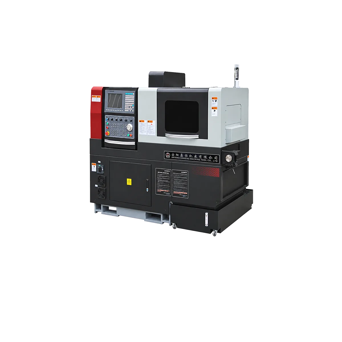


Oil pipe and casing machining places different demands on a lathe compared with ordinary shaft turning. The workpieces are usually long, hollow, relatively large in diameter, and require accurate pipe-end threads. For this reason, spindle bore, pipe threading range, chuck arrangement, low-speed cutting capability, and rear support are often more important than simply choosing a long machine bed.
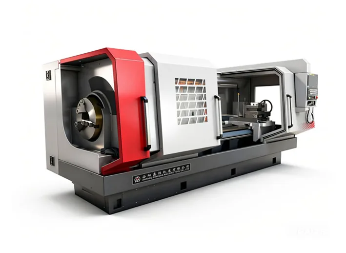
A CNC pipe threading lathe is specifically designed around these requirements and is widely used for oil-country tubular goods (OCTG), including casing and tubing. Xinheng’s QK series combines pipe threading with general CNC turning functions such as facing, boring, grooving, and drilling.
Industry
Oil and gas drilling requires tubular products to be connected section by section. Casing is used in the well structure, while tubing provides a flow path for oil and gas production.
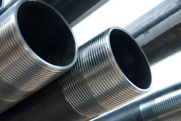
These long tubular components require machined connections at their ends. Depending on the application, the machining may involve external threads, internal threads, tapered threads, facing, boring, and other pipe-end features.
Xinheng’s CNC oil-country lathes are designed for applications including oil and gas drilling and high-pressure pipeline processing, and can machine API 5B, metric, imperial, and tapered threads.
Workpiece
Typical workpieces include:
When selecting the machine, the first parameters to check are usually:
Pipe OD → Wall Thickness → Pipe Length → Pipe Weight → Thread Size → Thread Standard
One important characteristic of oil pipe and casing is their length. A pipe may be 6, 8, 12, or 16 meters long, but this does not necessarily mean that an equally long lathe bed is required.
When only the pipe end needs machining, the pipe can pass through the hollow spindle and extend behind the headstock. Xinheng’s double-chuck pipe threading lathes are designed for long workpieces in these length ranges.
A suitable rear support can then be used to support the section extending behind the machine.
Process
A typical oil pipe or casing machining process may include:
Loading → Clamping → Facing → OD/ID Turning → Chamfering → Grooving → Thread Cutting → Inspection
The actual process depends on the pipe drawing and connection specification.
For casing and tubing threads, CNC control is particularly useful for repeated production. Once the machining program, tooling, and setup have been established, the machine can repeat the programmed thread cycle for subsequent workpieces.
The machine can also perform general CNC turning operations, allowing several pipe-end features to be completed without moving the workpiece to another conventional lathe.
Machine Requirements
Large Spindle Bore
The spindle bore must be large enough for the pipe to pass through the headstock.
However, spindle bore and pipe threading range are not the same specification. Both should be checked when selecting a model.
For example:
| Model | Pipe Threading Range | Spindle Bore |
| QK1219 | Φ50–193 mm | Φ200 mm |
| QK1222 | Φ50–220 mm | Φ225 mm |
| QK1225 | Φ50–250 mm | Φ255 mm |
| QK1227 | Φ50–270 mm | Φ280 mm |
Xinheng’s 550/600 mm guideway QK series covers pipe diameters from approximately Φ30 mm to Φ270 mm in its primary listed range.
Double-Chuck Clamping
Long pipes need stable support around the headstock. A double-chuck arrangement provides clamping at the front and rear of the spindle area, helping stabilize long tubular workpieces during threading.
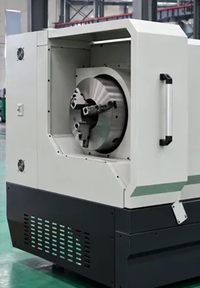
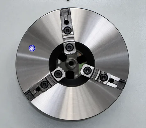
For higher production requirements, pneumatic or hydraulic double chucks can be used to automate clamping.
Suitable Spindle Speed and Torque
Large pipe threads are normally machined at relatively low spindle speeds. Therefore, buyers should not evaluate an oil-country lathe only by maximum spindle rpm.
The spindle system should provide suitable low-speed capability and cutting performance for the pipe diameter, material, thread pitch, and depth of cut.
Rear Pipe Support
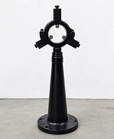
When several meters of pipe extend behind the headstock, proper support is important.
The rear support helps stabilize the pipe outside the machine and should be considered together with pipe diameter, length, weight, and spindle speed.
Recommended Model
For medium-size oil pipe and casing, models such as QK1219, QK1222, QK1225, and QK1227 provide different spindle bores and pipe-threading capacities. A documented QK1222 application, for example, uses a Φ50–220 mm pipe range and has been supplied for OCTG-related pipe-thread machining.
For larger casing and tubular components, moving to the heavier QK series may be necessary.
Xinheng’s 755 mm guideway CNC pipe-threading range includes:
| Model | Pipe Threading Range | Spindle Bore |
| QK1232 | Φ190–320 mm | Φ330 mm |
| QK1238 | Φ190–380 mm | Φ390 mm |
| QK1243 | Φ270–430 mm | Φ440 mm |
| QK1250 | Φ330–510 mm | Φ520 mm |
| QK1263 | Φ330–630 mm | Φ640 mm |
The QK1232–QK1250 configurations have a listed maximum workpiece capacity of 6 tons, while the QK1263 reaches 10 tons.
The larger series can also be configured with 3/4-jaw pneumatic or hydraulic chucks, 6/8/12-station electric or hydraulic turrets, hydraulic tailstock, hydraulic steady rest, rear support, chip conveyor, and automatic pipe loading/unloading equipment.
The correct model should therefore be selected according to the actual pipe—not simply by choosing the largest spindle bore.
Before requesting a quotation, provide the pipe OD and ID, wall thickness, total length, weight, material grade, thread standard, thread dimensions, machining allowance, workpiece drawing, and production quantity. Xinheng’s own selection guidance likewise recommends starting with spindle bore and chuck requirements when the application is oil pipe or casing machining.
For production planning, the most useful approach is:
Pipe drawing → Pipe diameter → Thread specification → Spindle bore → Chuck configuration → Rear support → Production quantity → CNC configuration